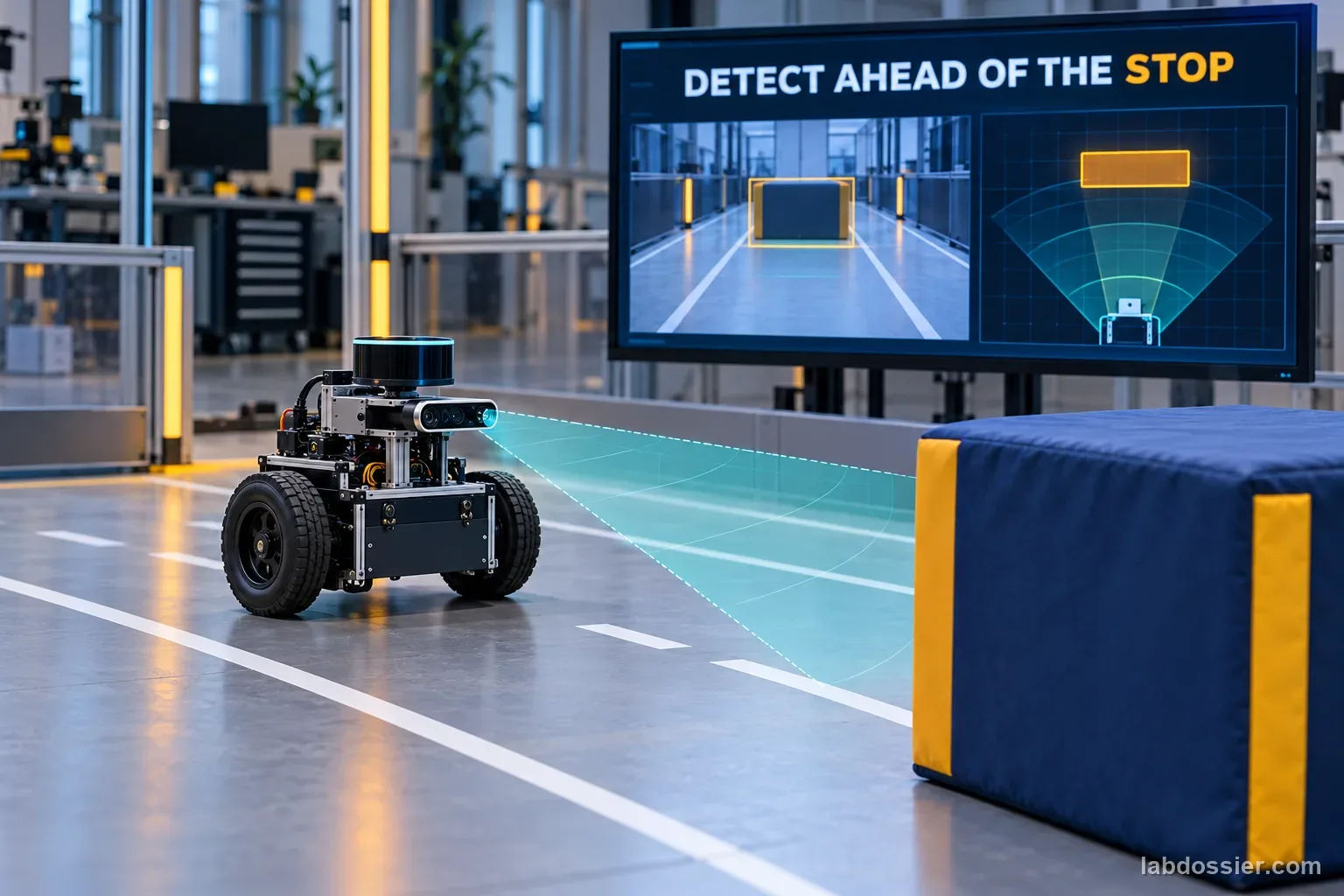
How far ahead must a mobile robot detect an obstacle to stop?
01 // Question
For a tested mobile robot, how did speed and maneuver change the estimated front-bumper reaction distance, and what extra evidence is needed to set an obstacle-detection field?
The paper measured distance to begin a maneuver; it did not test a sensor's obstacle-detection range, pipeline latency, moving obstacles or a certified protective field.
02 // Variables
Independent
Maneuver and commanded approach speed in one published differential-drive experiment- Hard brake
- Driven-inner-wheel arc
- Brake-assisted pivot
- Reverse spin
- Managed reverse spin
- 45, 55 or 65 cm/s commanded speed
Dependent
Fitted front-bumper reaction distance associated with 90% avoidance success in that study- Estimated d90 in centimeters
- 95% profile-likelihood interval
- Observed minimum clearance and success classification
03 // Hypothesis
IF a differential-drive robot approaches faster or uses a different braking/turning maneuver, THEN the required reaction distance and clearance may change, but a maneuver's fitted d90 is not the sensor's detection range, BECAUSE motion during control latency, braking distance, the rotating footprint, actuator response and uncertainty all affect when the obstacle must be detected.
04 // Procedure
1. Define the distance measured in the study
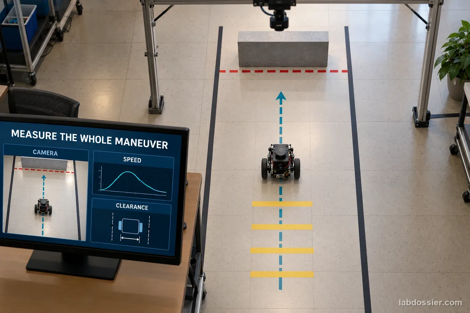
Read the 2026 preprint's methods before using its table. The study defines a commanded front-bumper reaction distance from the point a selected maneuver begins. It does not measure obstacle detection-to-stop distance: maneuvers are triggered after encoder-measured travel, and sensor-detection latency and moving obstacles are outside the experiment. The 90% figure is a fitted study outcome, not a safety certification target.
2. Copy the 15 speed–maneuver estimates
Transcribe all five maneuvers at 45, 55 and 65 cm/s, keeping each 95% profile interval beside its point estimate. The principal campaign retained 539 of 540 block-randomized trials on one differential-drive robot and one tile surface. Preserve the sample boundary and the one excluded trial; do not combine the study's earlier pilot campaigns with this dataset.
3. Compare speed and uncertainty
For each maneuver, subtract the 45 cm/s estimate from the 65 cm/s estimate and state the result in centimeters. Check whether intervals overlap, while avoiding the claim that overlap alone is a formal significance test. The study reports hard braking with the smallest point-estimate distance at each speed; turning does not reduce d90 below hard braking in this particular test. A commanded turn still serves a different task from stopping.
4. Separate sensing and stopping terms
Nav2's Collision Monitor guide gives a stop-zone distance model: d = v × tᵣ + v² ÷ (2a) + dₘ. Here tᵣ includes sensor period, command processing and base-driver latency; a is measured deceleration; and dₘ is a sensor-noise margin. Use consistent SI units. These terms describe travel after the system starts reacting; include the robot footprint and relevant geometry when setting a field. Do not substitute the study's d90 values for measured latency or deceleration.
5. Trace what the experiment does not include
Make a short boundary list: optical/range sensor detection limits, end-to-end control latency, sensor blind areas or occlusion, braking under the intended load/floor/battery, dynamic obstacles and a validated protective-field margin. The ISO 3691-4:2023 page describes a safety-requirements-and-verification scope for driverless industrial trucks including AMRs, and says a revision is in progress. The standard's full text is paid; this activity uses only the official public summary and does not claim any clause or compliance result.
6. Write a conclusion without inventing a safe distance
State the tested robot, tile surface, speed, maneuver, d90 estimate and interval. Then explain which additional system measurements would be required to estimate a sensor detection field. The paper's one-platform data can guide a question and a comparison, not certify a real robot. This lesson is published-data analysis; do not put a robot on a collision course or test it around people.
Materials // Prepare the bench
- 2026 differential-drive avoidance preprint
- Nav2 Collision Monitor guide
- ISO 3691-4 public summary
- calculator or spreadsheet
- run-level source table
05 // Data table
| Maneuver | Speed (cm/s) | Estimated front-bumper d90 (cm) | 95% profile interval (cm) |
|---|---|---|---|
| Hard brake (M0) | 45 | 3.8 | 2.7–5.9 |
| Hard brake (M0) | 55 | 5.0 | 4.3–6.5 |
| Hard brake (M0) | 65 | 7.6 | 6.4–9.7 |
| Driven-inner arc (M1) | 45 | 17.4 | 15.2–21.7 |
| Driven-inner arc (M1) | 55 | 15.9 | 14.9–17.6 |
| Driven-inner arc (M1) | 65 | 18.8 | 17.3–22.0 |
| Brake-assisted pivot (M2) | 45 | 9.8 | 8.4–12.0 |
| Brake-assisted pivot (M2) | 55 | 11.3 | 9.9–14.0 |
| Brake-assisted pivot (M2) | 65 | 14.1 | 12.3–17.8 |
| Reverse spin (M3) | 45 | 5.9 | 4.9–7.6 |
| Reverse spin (M3) | 55 | 7.9 | 6.9–9.6 |
| Reverse spin (M3) | 65 | 10.7 | 9.3–13.4 |
| Managed reverse spin (M4) | 45 | 7.1 | 6.0–9.4 |
| Managed reverse spin (M4) | 55 | 8.3 | 7.2–10.6 |
| Managed reverse spin (M4) | 65 | 12.8 | 10.9–16.6 |
What belongs in a measured stop envelope?
| Term | Evidence needed | Common mix-up |
|---|---|---|
| Reaction travel v × tᵣ | Measure sensor, software/command and driver latency together for the system | Using camera frame rate alone as end-to-end latency |
| Braking travel v² ÷ (2a) | Measure deceleration at relevant speed, surface, load and battery condition | Assuming a constant braking value from a different robot |
| Sensor/geometry margin dₘ | Document sensor uncertainty, detection limits and the robot's footprint | Treating nominal sensor range as a verified stop field |
| Moving obstacle / environment | Include relative motion, occlusion, floor and operating-zone conditions | Assuming a stationary obstacle on tile represents every use case |
Study d90 values: point estimates only (cm)
| Maneuver | 45 cm/s | 55 cm/s | 65 cm/s |
|---|---|---|---|
| Hard brake (M0) | 3.8 | 5.0 | 7.6 |
| Driven-inner arc (M1) | 17.4 | 15.9 | 18.8 |
| Brake-assisted pivot (M2) | 9.8 | 11.3 | 14.1 |
| Reverse spin (M3) | 5.9 | 7.9 | 10.7 |
| Managed reverse spin (M4) | 7.1 | 8.3 | 12.8 |
Formula Nav2 stop-zone model: d = v × tᵣ + v² ÷ (2a) + dₘ; v in m/s, tᵣ in s, a in m/s², and d/dₘ in m. Measure the actual system inputs; this is not a certified safe-distance result.
06 // What to expect
The 2026 study's fitted d90 values vary by maneuver and speed, but represent a commanded front-bumper maneuver distance under its specific robot/surface experiment.
Sensor range, stopping distance and an operating safety field are related but are not interchangeable quantities.
Latency, braking response, footprint, uncertainty, load, floor and moving obstacles need system-specific evidence before any protective distance is set.
07 // Lab notes
- ISO's official public page confirms ISO 3691-4:2023 scope and says a revision is in progress; the complete standard is paid. No requirements from inaccessible clauses are reproduced here.
08 // Remember
Know exactly where the distance starts and ends. A robot's measured maneuver distance is not its safe sensor range.
09 // An obstacle must be detected before the robot runs out of room
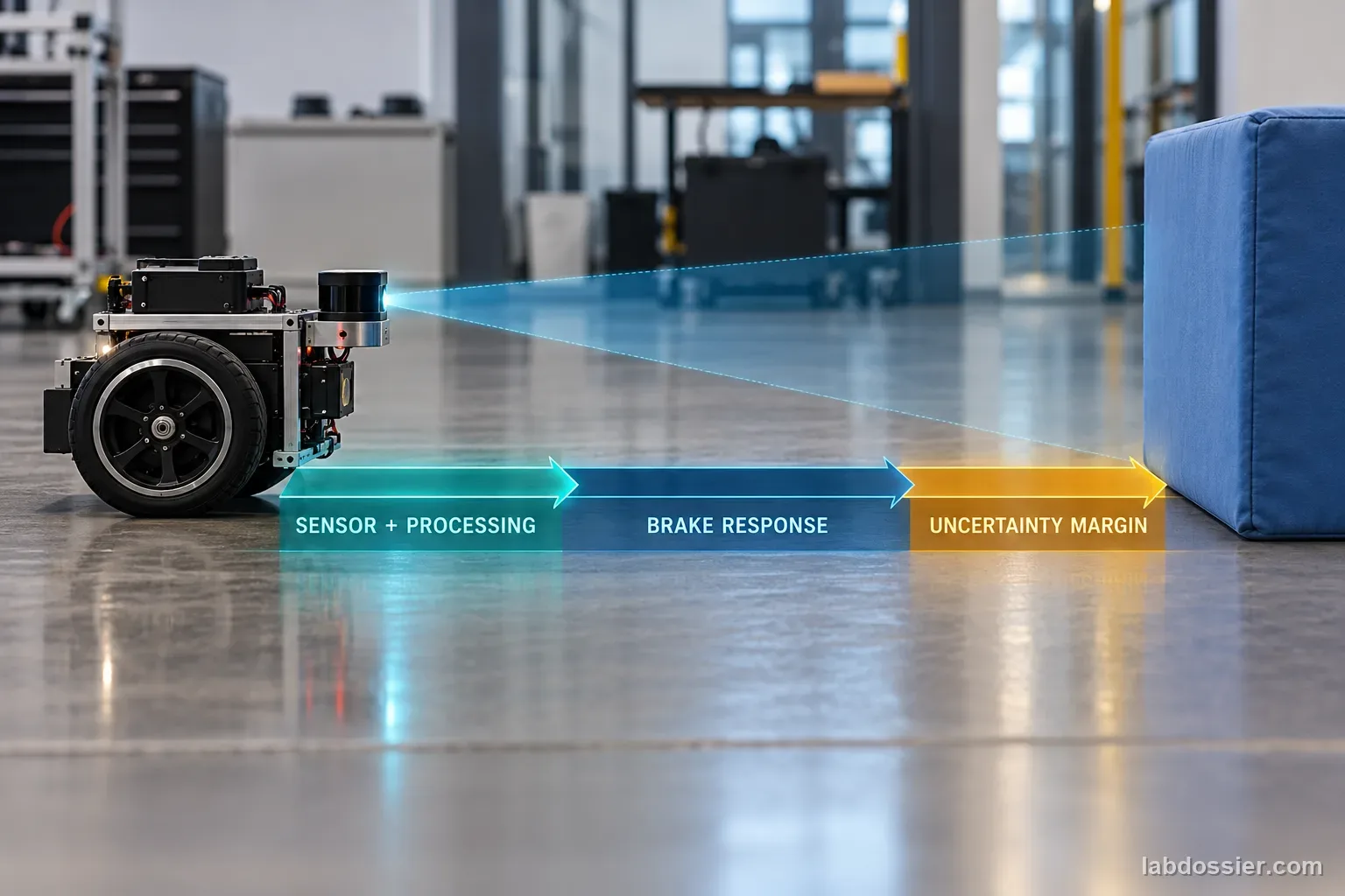
A sensor's advertised range is not the distance a mobile robot needs to stop. After the obstacle is observed, sensing, processing, command transport and the base driver take time. The robot keeps moving during that delay, then needs additional distance to brake. The robot's footprint, obstacle shape and measurement uncertainty also affect clearance.
Nav2's Collision Monitor guide models a stop-zone extension as d = v × tᵣ + v² ÷ (2a) + dₘ. It defines reaction time tᵣ to include sensor period, command-processing period and base-driver latency, and says to measure that time and deceleration on the robot. This engineering model helps organize measurements; it is not a universal safety distance or certification result.
10 // What the recent robot study measured
Mandve and Kant's October 2026 arXiv preprint reports a randomized study of five emergency maneuvers at commanded speeds of 45, 55 and 65 cm/s. Its principal campaign retained 539 of 540 trials on one Pololu Romi 32U4 and a tile surface, using overhead-camera pose measurements. The authors fit the front-bumper reaction distance associated with 90% avoidance success for each speed/maneuver condition and give 95% profile intervals.
The paper's d90 is the commanded bumper distance at maneuver initiation. It is not the sensor's measured detection range or a robot stopping distance. The experiment excludes sensor-detection latency and moving obstacles, uses one robot and surface, and has limited repeated trials per distance. Treat the table as a detailed case study, not an operational recommendation.
11 // Compare the speeds and maneuver types
For hard braking (M0), the fitted d90 estimates rise from 3.8 cm at 45 cm/s to 7.6 cm at 65 cm/s. The reverse spin (M3) rises from 5.9 cm to 10.7 cm, and the managed reverse spin (M4) from 7.1 cm to 12.8 cm. Their uncertainty intervals belong beside each point estimate; do not report only the center value.
The driven-inner arc (M1) is not monotonic in this sample: 17.4, 15.9 and 18.8 cm across the three speeds. Hard braking has the smallest point estimate at every tested speed, but it does not turn the robot toward a new heading. The study says the maneuver trade-off depends on task and distance, and does not claim a universal winner.
12 // Add the sensing and braking parts carefully
Keep the Nav2 stop-zone equation in consistent units: d = v × tᵣ + v² ÷ (2a) + dₘ, with v in m/s, tᵣ in seconds, a in m/s², and distances in meters. The first term is travel during reaction delay; the second is constant-deceleration braking distance; the final term represents a margin for sensor noise. The robot footprint and location from which distance is measured also matter.
The research study's d90 cannot fill in tᵣ, a or dₘ. It is measured from a different event and includes a maneuver rather than a pure straight stop. Do not add its values to an assumed latency estimate or label the sum a safe distance. A real design needs system-specific measurements and engineering validation under relevant speeds, loads, surfaces, sensor conditions and operating-zone rules.
13 // Use official safety sources within their limits
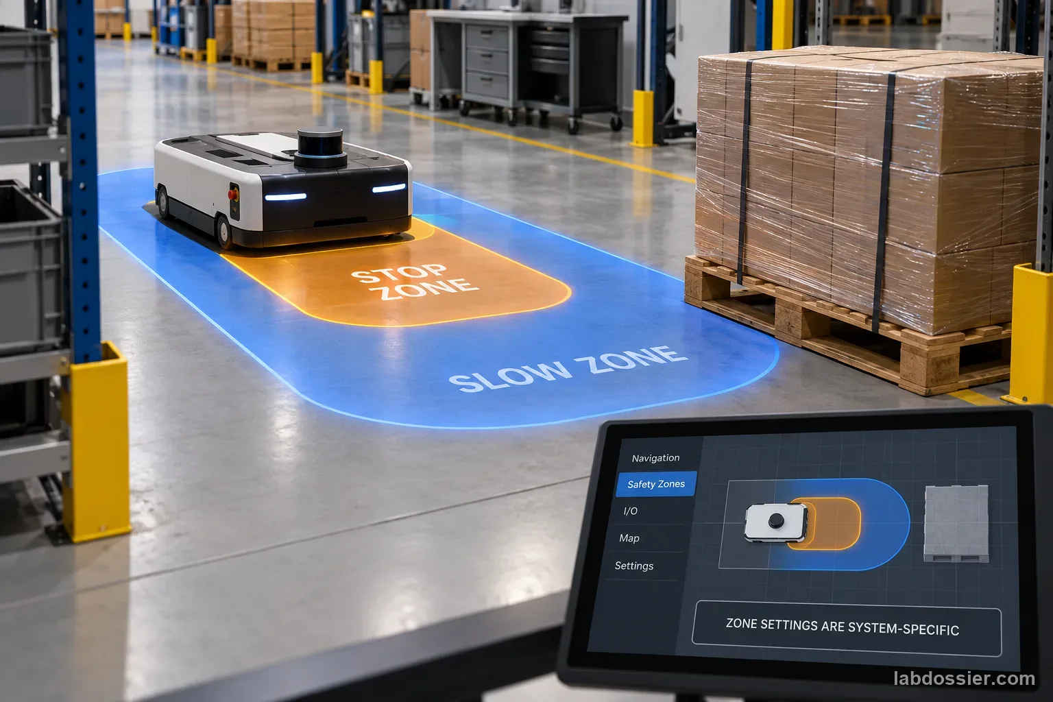
The Nav2 documentation demonstrates configurable slow and stop zones, including velocity-dependent zones. Its example polygons and distances are software examples, not settings to copy for another robot. The guide explicitly calls for measuring reaction time and deceleration on the actual platform and accounting for a sensor margin.
ISO's public page describes ISO 3691-4:2023 as safety requirements and verification for driverless industrial trucks, including AMRs, and shows that the standard is under revision. The full standard is paid; this page does not expose enough text to support claims about a specific stopping-distance clause. A classroom robot exercise cannot establish compliance with it.
14 // Questions people ask
Is the study's d90 the minimum sensor detection distance?
No. It is an estimated commanded front-bumper distance to start a maneuver for a 90% fitted success level in one test. The study excludes detection latency and moving obstacles.
Why does speed change stopping distance so much?
Reaction travel grows with speed and braking travel grows with speed squared under a constant-deceleration approximation. The actual system also has sensor/control latency, footprint and uncertainty to account for.
Can the Nav2 tutorial's sample stop-zone dimensions be reused?
No. Its examples demonstrate software configuration. The same guide says to measure reaction time and deceleration on the robot and account for sensor margin; example zone sizes are not safety settings for another system.
Does the ISO page tell me a specific detection distance?
The public summary describes ISO 3691-4:2023 scope and verification, not a universal distance. The complete standard is paid and its revision is in progress, so this article does not claim a specific clause or distance.
Can I test this by placing a person in front of a robot?
No. Use the published dataset or simulator. Real protective-distance validation belongs to an authorized, guarded test environment with trained safety professionals.
15 // Keep going
Can you explain the investigation?
How far ahead must a mobile robot detect an obstacle to stop? · Student Data Sheet
Question: For a tested mobile robot, how did speed and maneuver change the estimated front-bumper reaction distance, and what extra evidence is needed to set an obstacle-detection field?
Hypothesis: If a differential-drive robot approaches faster or uses a different braking/turning maneuver, then the required reaction distance and clearance may change, but a maneuver's fitted d90 is not the sensor's detection range, because motion during control latency, braking distance, the rotating footprint, actuator response and uncertainty all affect when the obstacle must be detected.
Materials
- 2026 differential-drive avoidance preprint
- Nav2 Collision Monitor guide
- ISO 3691-4 public summary
- calculator or spreadsheet
- run-level source table
Safety before starting
- This lesson analyzes published trial data. Do not command a robot toward a person, animal, or unguarded obstacle; do not bypass a protective stop or use foam as a substitute for an engineered safeguard.
- The paper's d90 estimates and the Nav2 equation are not a safe-distance setting. Never copy them to a classroom or workplace robot. Real protective-field design and validation require authorization, manufacturer instructions, a guarded test area, and qualified robotics/safety professionals.
Lab notes
- ISO's official public page confirms ISO 3691-4:2023 scope and says a revision is in progress; the complete standard is paid. No requirements from inaccessible clauses are reproduced here.
Variables
Independent: Maneuver and commanded approach speed in one published differential-drive experiment · Dependent: Fitted front-bumper reaction distance associated with 90% avoidance success in that study
Keep constant: same Pololu Romi 32U4 robot · tile surface · fixed maneuver parameters · overhead camera reference · block-randomized design · the paper's commanded front-bumper distance definition
Procedure
- Define the distance measured in the study: Read the 2026 preprint's methods before using its table. The study defines a commanded front-bumper reaction distance from the point a selected maneuver begins. It does not measure obstacle detection-to-stop distance: maneuvers are triggered after encoder-measured travel, and sensor-detection latency and moving obstacles are outside the experiment. The 90% figure is a fitted study outcome, not a safety certification target.
- Copy the 15 speed–maneuver estimates: Transcribe all five maneuvers at 45, 55 and 65 cm/s, keeping each 95% profile interval beside its point estimate. The principal campaign retained 539 of 540 block-randomized trials on one differential-drive robot and one tile surface. Preserve the sample boundary and the one excluded trial; do not combine the study's earlier pilot campaigns with this dataset.
- Compare speed and uncertainty: For each maneuver, subtract the 45 cm/s estimate from the 65 cm/s estimate and state the result in centimeters. Check whether intervals overlap, while avoiding the claim that overlap alone is a formal significance test. The study reports hard braking with the smallest point-estimate distance at each speed; turning does not reduce d90 below hard braking in this particular test. A commanded turn still serves a different task from stopping.
- Separate sensing and stopping terms: Nav2's Collision Monitor guide gives a stop-zone distance model: d = v × tᵣ + v² ÷ (2a) + dₘ. Here tᵣ includes sensor period, command processing and base-driver latency; a is measured deceleration; and dₘ is a sensor-noise margin. Use consistent SI units. These terms describe travel after the system starts reacting; include the robot footprint and relevant geometry when setting a field. Do not substitute the study's d90 values for measured latency or deceleration.
- Trace what the experiment does not include: Make a short boundary list: optical/range sensor detection limits, end-to-end control latency, sensor blind areas or occlusion, braking under the intended load/floor/battery, dynamic obstacles and a validated protective-field margin. The ISO 3691-4:2023 page describes a safety-requirements-and-verification scope for driverless industrial trucks including AMRs, and says a revision is in progress. The standard's full text is paid; this activity uses only the official public summary and does not claim any clause or compliance result.
- Write a conclusion without inventing a safe distance: State the tested robot, tile surface, speed, maneuver, d90 estimate and interval. Then explain which additional system measurements would be required to estimate a sensor detection field. The paper's one-platform data can guide a question and a comparison, not certify a real robot. This lesson is published-data analysis; do not put a robot on a collision course or test it around people.
Record your observations
| Maneuver | Speed (cm/s) | Estimated front-bumper d90 (cm) | 95% profile interval (cm) |
|---|---|---|---|
What belongs in a measured stop envelope?
| Term | Evidence needed | Common mix-up |
|---|---|---|
Study d90 values: point estimates only (cm)
| Maneuver | 45 cm/s | 55 cm/s | 65 cm/s |
|---|---|---|---|
Formula: Nav2 stop-zone model: d = v × tᵣ + v² ÷ (2a) + dₘ; v in m/s, tᵣ in s, a in m/s², and d/dₘ in m. Measure the actual system inputs; this is not a certified safe-distance result.
Answer key and expected pattern
The 2026 study's fitted d90 values vary by maneuver and speed, but represent a commanded front-bumper maneuver distance under its specific robot/surface experiment.
Sensor range, stopping distance and an operating safety field are related but are not interchangeable quantities.
Latency, braking response, footprint, uncertainty, load, floor and moving obstacles need system-specific evidence before any protective distance is set.
Remember: Know exactly where the distance starts and ends. A robot's measured maneuver distance is not its safe sensor range.