How does the Sun's angle change a Moon-surface shadow?
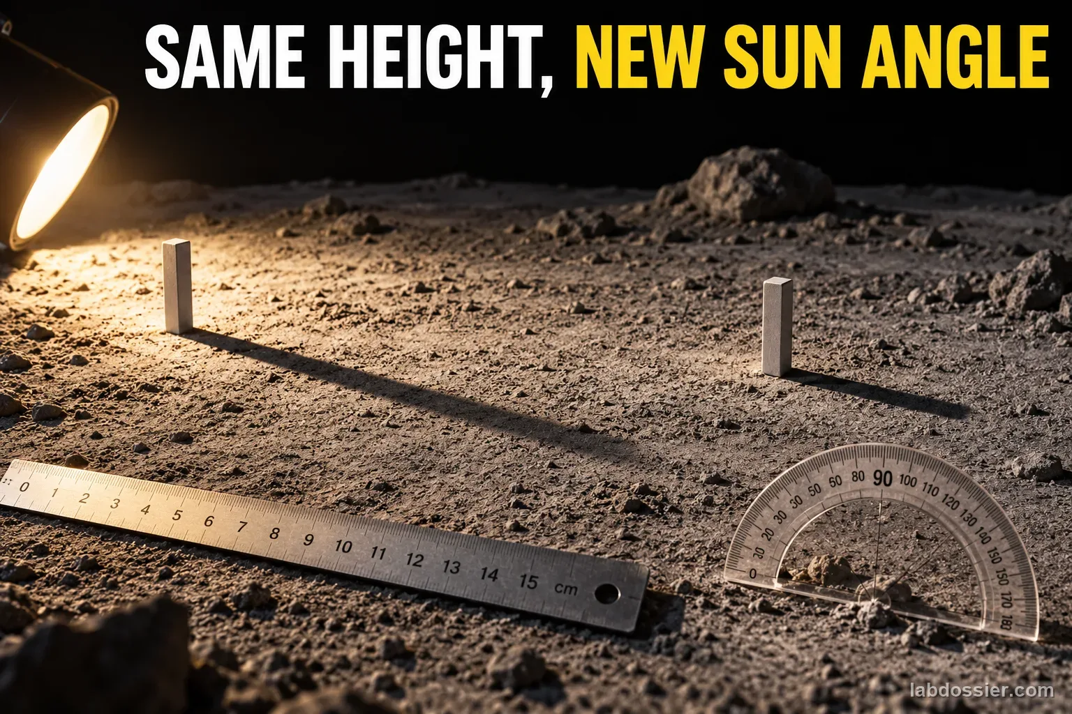
01 // Question
For the same vertical feature on a level surface, how does changing solar elevation change shadow length, and why can lunar crater shadows behave differently?
The classroom geometry is an ideal flat-ground, parallel-ray model. It helps interpret lunar shadows but does not measure a real crater or predict a mission site by itself.
02 // Variables
Independent
Sun elevation above the level ground in the geometry model- 15°
- 30°
- 45°
- 60°
Dependent
Calculated and ruler-checked shadow length for one 6 cm vertical model feature- Predicted length from L = H / tan(α)
- Scale drawing length using the stated scale
- Difference between ideal geometry and the lunar terrain examples
03 // Hypothesis
IF Sun elevation α decreases while the vertical height and flat ground remain fixed, THEN the ideal model's shadow length will increase, BECAUSE the vertical height and horizontal shadow form a right triangle with tan(α) = H/L, so L = H/tan(α).
04 // Procedure
1. Set the ideal lunar-surface model
On graph paper, draw a horizontal ground line and one 6 cm vertical marker. Label α as the angle between the incoming light ray and the ground. Assume the rays are parallel and the marker is perpendicular to a flat surface. This geometric model has no nearby lamp, slope or crater wall.
2. Predict the four shadow lengths
For α = 15°, 30°, 45° and 60°, calculate L = H/tan(α) using H = 6 cm. Keep the calculator in degree mode. Round calculated lengths to the nearest 0.1 cm only after calculating, and record the unrounded result if your class compares rounding choices.
3. Draw and check at one scale
Use a consistent drawing scale of 1 drawing cm per 4 cm of model length. Draw the vertical marker as 1.5 cm and construct the light ray at each stated angle using a protractor; extend the ground shadow from the marker base to the ray intersection. Measure each drawing with a ruler and convert back to model centimeters. The longest case needs a page wide enough for the full ray and shadow; use tiled graph paper if needed.
4. Compare angle cases without changing height
Add the predicted and scale-checked lengths to the table. Plot solar elevation on the horizontal axis and shadow length on the vertical axis. The relationship is curved, not a constant subtraction per degree. Check whether the measured drawing agrees with the tangent calculation within your ruler and drawing precision.
5. Inspect NASA's real polar illumination evidence
Use NASA's LOLA-derived polar illumination maps or its south-pole visualization to identify a nearby sunlit ridge and shadowed crater floor. The real product models uneven topography and changing solar azimuth over time. It is not the same as the classroom's single vertical post, one flat plane and four fixed angles.
6. State the model's boundary
Explain why the classroom formula cannot determine whether a real crater floor is lit from shadow length alone: crater walls and ridges have changing slopes, the Sun's direction sweeps around the poles, and time and terrain elevation matter. NASA's Artemis lighting brief gives an approximate polar shadow rule of about 27 times object height near 1.5°–2° solar inclination; treat that as a rounded operational illustration, not as the exact output for every site or as a replacement for terrain modeling.
Materials // Prepare the bench
- graph paper or large paper sheets
- ruler
- protractor
- calculator set to degree mode
- NASA LOLA illumination map or NASA south-pole visualization
05 // Data table
| Solar elevation α | Height H | Calculated L = H/tan(α) | Scale drawing length (1:4) | Converted length | Check / note |
|---|---|---|---|---|---|
| 15° | 6.0 cm | 22.4 cm | |||
| 30° | 6.0 cm | 10.4 cm | |||
| 45° | 6.0 cm | 6.0 cm | |||
| 60° | 6.0 cm | 3.5 cm |
What the model includes and what NASA has to model
| Ideal drawing | Lunar polar terrain |
|---|---|
| Flat, level ground | Crater walls, ridges, slopes and irregular terrain |
| One vertical feature and one Sun elevation | Many topographic points under changing Sun elevation and azimuth |
| Parallel rays and sharp marker edge | Extended solar disk, local horizon, sensor resolution and surface scattering |
| One instant | Time series and seasonal/orbital illumination over the selected site |
Formula tan(α) = H / L, so L = H / tan(α). Here α is solar elevation measured up from level ground, H is vertical feature height, and L is the horizontal shadow length.
06 // What to expect
For the same 6 cm vertical feature on ideal level ground, the shadow is longest at 15° and shortest at 60°; lower solar elevation produces a longer horizontal shadow.
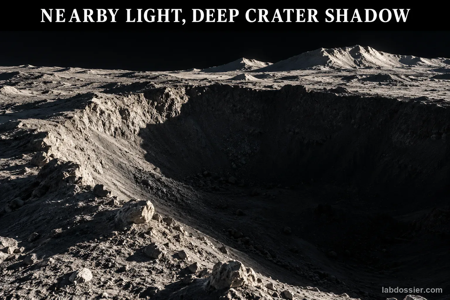
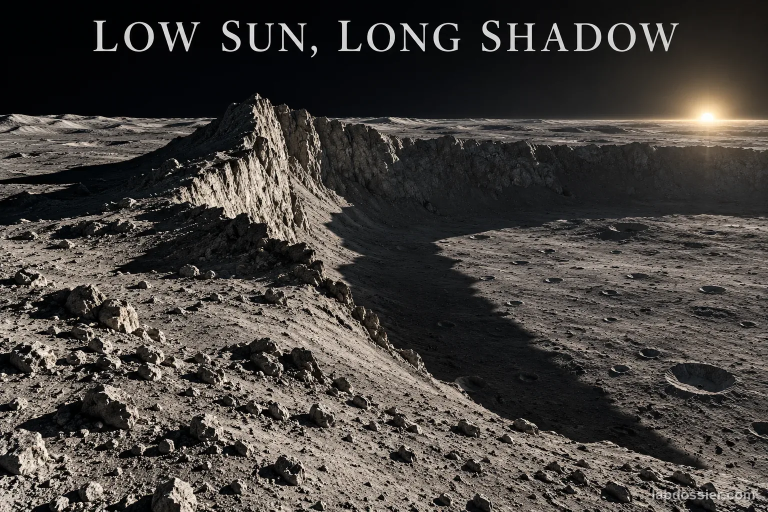
A crater floor may remain in shadow even while a nearby rim receives sunlight because terrain blocks the low-angle rays; the shadow direction also changes as the Sun's azimuth sweeps around the polar horizon.
The ideal equation describes one right triangle, not an entire lunar site. Mission-scale illumination products combine topography, the Sun's position and time.
07 // Lab notes
- The given four calculated lengths are predictions from ideal right-triangle geometry, not measurements from the Moon or a lamp experiment.
- NASA's Artemis lighting brief describes about 27H of shadow for an approximate 1.5°–2° polar Sun inclination. Its value is explicitly approximate; use the equation with a stated angle for ideal geometry and do not silently force the two into exact agreement.
- At the lunar poles, solar azimuth changes as well as elevation. Long shadow direction, terrain slope and nearby obstruction matter in addition to a single angle.
08 // Remember
Lower Sun, longer ideal shadow—but lunar terrain makes each site more complicated. Use L = H/tan(α) only when height, level ground, vertical feature and light direction satisfy the right-triangle model; use terrain and time data for real lunar illumination.
09 // Why a polar shadow can stretch far beyond its object
NASA's Artemis lighting brief treats lunar shadow length as a geometry and operations problem. It explains that the polar Sun skims close to the horizon and notes an approximate rule of about 27 times an object's height for one stated low-Sun range. That estimate communicates scale; it is not an exact result for every angle, terrain slope or location.
For one vertical object on level ground, define α as the Sun's elevation above the ground. The object's height H and horizontal shadow L form a right triangle, so tan(α) = H/L and L = H/tan(α). As α approaches the horizon, tan(α) becomes small and the ideal shadow grows rapidly.
10 // What NASA's lunar data add to the triangle
A real polar region is not one level plane. NASA's LOLA team uses high-precision lunar topography to model solar illumination across the terrain and over time. Its products show that average illumination over a long lunar nutation cycle can help find candidate sites, but shorter periods, higher resolution and height above the surface can require additional analysis.
NASA's Scientific Visualization Studio shows simulated south-pole illumination rendered at two-hour intervals using LRO laser-altimeter terrain data. The animation follows the Sun-shadow pattern through multiple years. It demonstrates why solar azimuth and time matter along with elevation: as the direction shifts around the horizon, shadows sweep across ridges and crater floors.
11 // A nearby ridge can change a crater floor's light
NASA's South Pole illumination map stacks 1,700 LROC images collected over six months; each mapped image marks pixels as illuminated or shadowed before the observations are combined into a percentage-of-time map. This is a time-aware, image-derived map, not a ruler measurement from one photograph.
The classroom calculation predicts one shadow behind one vertical marker. It cannot decide whether a particular crater is permanently shadowed. Local slopes, rim height, the full surrounding horizon, solar azimuth and the selected time window must be considered. Keep that boundary visible when connecting the paper model to real lunar maps.
12 // Treat the low-angle rule as an estimate
The four classroom predictions use the exact tangent relationship for four chosen angles and one stated height. NASA's brief gives a rounded operational example of about 27H at approximately 1.5°–2°. It is useful context, not a substitute for choosing one exact α and calculating the ideal triangle. Real crater terrain also violates the flat-ground and single-feature assumptions.
If the drawn and calculated lengths differ, first check degree mode, which side of α is opposite/adjacent, whether the feature is vertical, and how the shadow endpoint was defined. Report measurement or drawing uncertainty instead of editing results to match NASA's approximate rule.
13 // Questions people ask
Why does a lower Sun make the same object's shadow longer?
For a vertical object on flat ground, the height and shadow make a right triangle. Since tan(α) = H/L, lowering α increases L when H stays fixed.
What does the angle α measure?
In this activity it is solar elevation: the angle from the level ground up to the light ray. It is not the angle from the vertical. Near the lunar horizon, α is small and the ideal shadow is long.
Why can a crater floor stay dark while nearby terrain is illuminated?
A raised crater rim or nearby ridge can block very low-angle sunlight from reaching the floor. NASA's LOLA-based models combine topography with illumination over time to identify such regions.
Does the equation predict every lunar shadow exactly?
No. It assumes a flat level surface, one vertical feature, parallel rays and a single solar elevation. Real terrain has slopes, complex horizons and a changing solar azimuth; the Sun also has a finite apparent size.
Is NASA's 27-times-height shadow rule the exact result for 1.5 degrees?
No. NASA calls it an approximate rule for a stated polar inclination range. Calculate an ideal length from the exact chosen angle for the classroom triangle, and keep NASA's operational example labeled as approximate.
Can you explain the investigation?
How does the Sun's angle change a Moon-surface shadow? · Student Data Sheet
Question: For the same vertical feature on a level surface, how does changing solar elevation change shadow length, and why can lunar crater shadows behave differently?
Hypothesis: If Sun elevation α decreases while the vertical height and flat ground remain fixed, then the ideal model's shadow length will increase, because the vertical height and horizontal shadow form a right triangle with tan(α) = H/L, so L = H/tan(α).
Materials
- graph paper or large paper sheets
- ruler
- protractor
- calculator set to degree mode
- NASA LOLA illumination map or NASA south-pole visualization
Safety before starting
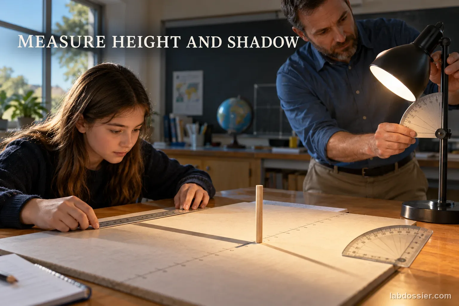
- This activity uses geometry drawings and published NASA imagery. If a desk lamp is used for a demonstration, choose a cool, stable lamp and keep it away from paper and flammable materials; switch it off before moving it.
- Never look at or point cameras, binoculars, telescopes, lasers or other optics toward the Sun. Do not use a laser as a light source in this lesson.
- Keep large graph paper, rulers and protractors on a stable desk; clear cables and bags from walkways. Use NASA's published shadow imagery if a safe setup is unavailable.
Lab notes
- The given four calculated lengths are predictions from ideal right-triangle geometry, not measurements from the Moon or a lamp experiment.
- NASA's Artemis lighting brief describes about 27H of shadow for an approximate 1.5°–2° polar Sun inclination. Its value is explicitly approximate; use the equation with a stated angle for ideal geometry and do not silently force the two into exact agreement.
- At the lunar poles, solar azimuth changes as well as elevation. Long shadow direction, terrain slope and nearby obstruction matter in addition to a single angle.
Variables
Independent: Sun elevation above the level ground in the geometry model · Dependent: Calculated and ruler-checked shadow length for one 6 cm vertical model feature
Keep constant: Keep feature height at 6 cm, ground horizontal, feature vertical, light azimuth fixed, and the same ray/measurement convention; change solar elevation only
Procedure
- Set the ideal lunar-surface model: On graph paper, draw a horizontal ground line and one 6 cm vertical marker. Label α as the angle between the incoming light ray and the ground. Assume the rays are parallel and the marker is perpendicular to a flat surface. This geometric model has no nearby lamp, slope or crater wall.
- Predict the four shadow lengths: For α = 15°, 30°, 45° and 60°, calculate L = H/tan(α) using H = 6 cm. Keep the calculator in degree mode. Round calculated lengths to the nearest 0.1 cm only after calculating, and record the unrounded result if your class compares rounding choices.
- Draw and check at one scale: Use a consistent drawing scale of 1 drawing cm per 4 cm of model length. Draw the vertical marker as 1.5 cm and construct the light ray at each stated angle using a protractor; extend the ground shadow from the marker base to the ray intersection. Measure each drawing with a ruler and convert back to model centimeters. The longest case needs a page wide enough for the full ray and shadow; use tiled graph paper if needed.
- Compare angle cases without changing height: Add the predicted and scale-checked lengths to the table. Plot solar elevation on the horizontal axis and shadow length on the vertical axis. The relationship is curved, not a constant subtraction per degree. Check whether the measured drawing agrees with the tangent calculation within your ruler and drawing precision.
- Inspect NASA's real polar illumination evidence: Use NASA's LOLA-derived polar illumination maps or its south-pole visualization to identify a nearby sunlit ridge and shadowed crater floor. The real product models uneven topography and changing solar azimuth over time. It is not the same as the classroom's single vertical post, one flat plane and four fixed angles.
- State the model's boundary: Explain why the classroom formula cannot determine whether a real crater floor is lit from shadow length alone: crater walls and ridges have changing slopes, the Sun's direction sweeps around the poles, and time and terrain elevation matter. NASA's Artemis lighting brief gives an approximate polar shadow rule of about 27 times object height near 1.5°–2° solar inclination; treat that as a rounded operational illustration, not as the exact output for every site or as a replacement for terrain modeling.
Record your observations
| Solar elevation α | Height H | Calculated L = H/tan(α) | Scale drawing length (1:4) | Converted length | Check / note |
|---|---|---|---|---|---|
What the model includes and what NASA has to model
| Ideal drawing | Lunar polar terrain |
|---|---|
Formula: tan(α) = H / L, so L = H / tan(α). Here α is solar elevation measured up from level ground, H is vertical feature height, and L is the horizontal shadow length.
Answer key and expected pattern
For the same 6 cm vertical feature on ideal level ground, the shadow is longest at 15° and shortest at 60°; lower solar elevation produces a longer horizontal shadow.
A crater floor may remain in shadow even while a nearby rim receives sunlight because terrain blocks the low-angle rays; the shadow direction also changes as the Sun's azimuth sweeps around the polar horizon.
The ideal equation describes one right triangle, not an entire lunar site. Mission-scale illumination products combine topography, the Sun's position and time.
Remember: Lower Sun, longer ideal shadow—but lunar terrain makes each site more complicated. Use L = H/tan(α) only when height, level ground, vertical feature and light direction satisfy the right-triangle model; use terrain and time data for real lunar illumination.