How does magnetic-field strength change the predicted force on an identical simulated charged particle?
01 // Question
For the same hypothetical charged particle and perpendicular motion, how does a change in measured magnetic-field strength change the magnetic-force proxy?
This is a field-strength and equation model, not a simulation of solar-wind plasma, a planetary magnetosphere, particle radiation or atmospheric protection. A small bar magnet is not a scale model of Earth or Mars.
02 // Variables
Independent
Measured magnetic-field magnitude at one fixed sensor point, changed by using different teacher-approved magnet configurations- Three field settings in the same direction: low, medium and high
- At least five stabilized readings at each setting
- A fixed probe position and orientation marked before collection
Dependent
Relative magnetic-force proxy for the same hypothetical charged particle moving at 90° to the field- B-perpendicular in microteslas at the probe
- Relative force proxy B divided by the lowest-setting B
- Optional predicted gyroradius ratio, which is inversely proportional to B when charge, mass and perpendicular speed are held fixed
03 // Hypothesis
IF the measured magnetic-field strength increases while the hypothetical particle, speed and 90° motion angle remain fixed, THEN the calculated magnetic-force-per-unit-charge-speed proxy will increase in direct proportion to the measured field, BECAUSE the magnetic part of the Lorentz force has magnitude |q|vB sin θ, so at 90° the sine term is one and the field magnitude is the changing factor.
04 // Procedure
1. Set up a low-risk field measurement
Use a classroom Hall-effect magnetometer or a phone sensor only if its sensor type and units are known. Keep phones, magnetic storage media, watches and medical devices away from strong magnets; follow the device maker's guidance. Do not use loose iron filings, projectile particles, high-voltage equipment or powerful neodymium magnets. Mark one probe point on a nonmagnetic stand and record the probe axis.
2. Choose three controlled field settings
Use teacher-approved small classroom magnets arranged to produce the same field direction at the marked point. Change one spacing or configuration variable to create low, medium and high settings; keep the probe, support and surrounding objects fixed. If changing the configuration rotates the field, record direction as well as magnitude and do not compare magnitudes as if direction were unchanged.
3. Collect repeated sensor readings
Allow the sensor reading to settle, then record five values for each setting without touching the probe. Use the same averaging interval and remove or record the background field with the magnets absent. Keep every raw value; flag sensor overload, drift or a moved probe rather than silently deleting the reading. Calculate each setting's mean and range.
4. Calculate only the bounded force proxy
For a hypothetical particle moving at 90° to the measured field, the magnetic-force magnitude is |q|vB. Because the classroom sensor does not provide a real solar particle's charge or speed, compare B-perpendicular itself or divide each reading by the lowest-setting reading. The ratio is a relative force proxy only when the same q and v are assumed; it is not a force in newtons, an observed particle path or a shielding score.
5. Compare the equation model with NASA evidence
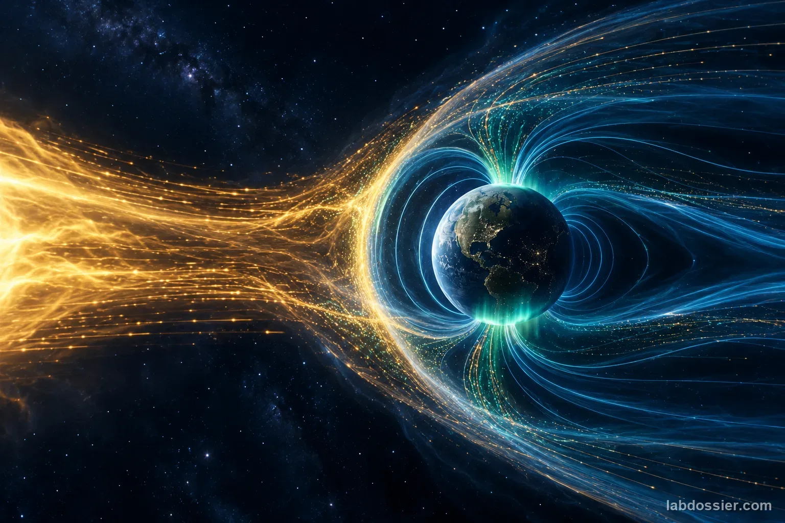
NASA describes Earth's magnetosphere as a large magnetic environment that interacts with solar wind. Its TRACERS mission measures changing reconnection events near the polar cusps, where particles can enter the near-Earth environment. NASA's 2026 MAVEN result describes much smaller, localized crustal magnetic structures at Mars and auroras associated with a miniature Dungey-like cycle. These observations show why a field does not simply repel every particle in the same way.
6. Write the boundary before the conclusion
State that the controlled result is the relationship between a measured field and a mathematical force proxy for one fixed hypothetical particle. Real solar-wind motion depends on particle charge, mass, speed, pitch angle, electric and magnetic fields, plasma interactions, field geometry and time-varying reconnection. Magnetic forces act perpendicular to velocity and can bend or guide motion; they do no work on an ideal isolated particle by themselves and are not a universal barrier.
Materials // Prepare the bench
- teacher-approved small classroom bar magnets
- Hall-effect field sensor or phone with a verified magnetometer and units
- nonmagnetic probe stand and marked spacer
- ruler, tape, calculator and raw-data sheet
05 // Data table
| Field setting | Raw B readings (µT) | Mean B (µT) | Range (µT) | Relative B / low setting | Sensor or setup note |
|---|---|---|---|---|---|
| Low | 1.00 | ||||
| Medium | |||||
| High |
What the force equation does and does not predict
| Case | Model relationship | Interpretation limit |
|---|---|---|
| Motion perpendicular to field (90°) | F = |q|vB; force proxy grows in proportion to B if q and v are fixed | Does not predict real solar-particle force without its charge and velocity |
| Motion partly along field | F = |q|vB sin θ; only the perpendicular velocity contributes | Field-parallel motion is not bent by the magnetic part of the Lorentz force |
| Motion parallel to field (0°) | Magnetic force is zero in the ideal equation | Electric fields and plasma interactions may still matter in space |
| Planetary magnetic environment | Field geometry can guide, trap, or redirect charged particles | Not a solid wall; reconnection and other processes can allow energy and particles to enter |
A bar magnet, Earth and Mars are different systems
| System | What the source or model supports | What it cannot establish |
|---|---|---|
| Classroom bar magnet and Hall sensor | Local field magnitude at a marked point and a controlled B comparison | Planet-scale field geometry, solar-wind interaction or radiation protection |
| Earth and TRACERS | A global magnetosphere interacts with solar wind; reconnection and polar cusps are measured processes | That every particle is turned away or that the magnetosphere is an impermeable shield |
| Mars and MAVEN | Localized crustal magnetic regions can host complex interactions and aurora | A current global Martian magnetic field like Earth's |
06 // What to expect
If the probe geometry and field direction stay controlled, a higher measured B produces a proportionally higher force proxy for the same hypothetical charge and speed at 90°.
The relationship changes with angle: field-parallel motion has no magnetic force in the simple Lorentz-force equation, while perpendicular motion has the largest magnetic-force magnitude for the same speed.
The result is a mathematical comparison based on a local magnet measurement, not a simulated solar-particle stream or a measure of planetary shielding.
07 // Lab notes
- For a charged particle, magnetic-force magnitude depends on charge, speed, field strength and the angle between velocity and field: F = |q|vB sin θ. Do not omit the angle or say every particle is repelled.
- Magnetic fields can guide, bend or trap charged particles. Earth's magnetosphere has polar cusps and reconnection; NASA has observed highly localized magnetic structures and auroras at Mars.
- A Hall sensor and tabletop magnet measure only a local classroom field. Never convert the reading directly into planetary field strength, particle radiation dose, atmospheric loss or human safety.
08 // Remember
A magnetic field can bend charged-particle motion, but a stronger classroom magnet does not reproduce a planet's space environment. Interpret the data as a B-dependent force proxy for an identical hypothetical particle, then use NASA observations to explain geometry, reconnection and the limits of the simple model.
09 // A magnetic field changes motion according to direction
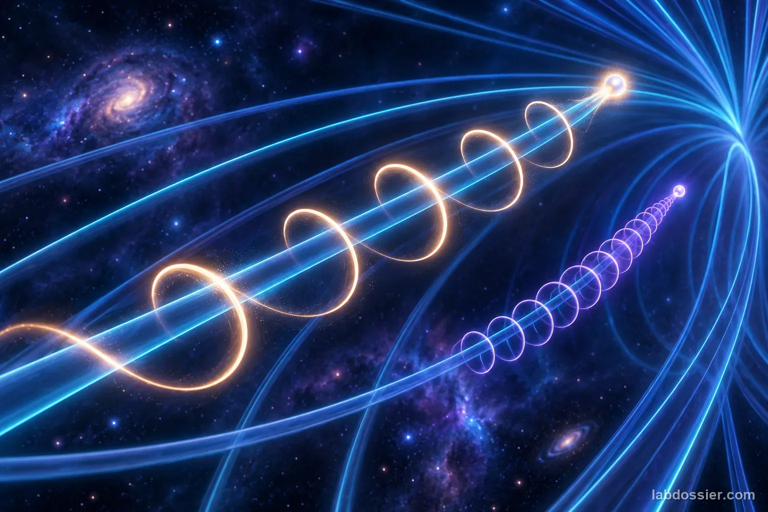
The magnetic part of the Lorentz force has magnitude F = |q|vB sin θ, where q is charge, v is speed, B is field strength and θ is the angle between motion and field. A stronger field increases magnetic force when q, v and angle stay fixed. At 90 degrees the magnetic force is largest for that speed; for motion parallel to the field, it is zero in this ideal relationship.
The force is perpendicular to velocity, so a magnetic field can bend a path without directly speeding an isolated particle up. In a real plasma, electric fields and particle interactions also matter. A field is not a simple wall that pushes every particle away.
10 // Set up a low-risk field measurement
Use a Hall sensor to record a local field at one marked point. A phone magnetometer may work if its sensor axis and units are known, but cases, speakers, steel furniture and compass calibration can affect the reading. Hold the probe on a nonmagnetic stand and keep its orientation fixed.
This setup excludes filings, loose metal particles, projectile demonstrations, high voltage and powerful magnets. It measures a local field near a small classroom magnet; it does not reproduce a planet-scale magnetosphere.

11 // Measure a local field with repeats
Take five stabilized readings for each of three teacher-approved field settings. Change only the marked spacing or magnet arrangement needed to adjust the field, and record direction if the arrangement changes it. Include a background reading with magnets removed. Calculate mean and range, then compare raw values for drift or inconsistent probe placement.
If readings approach the sensor range limit, show overload in the notes and choose a lower-field setup. Do not discard outliers after seeing whether they support the hypothesis; apply a repeat or exclusion rule chosen beforehand.
12 // Calculate only the bounded force proxy
At a fixed 90-degree angle, F = |q|vB. Since the activity does not measure a real particle's charge or speed, compare measured B values as relative force proxies. If the medium reading is twice the low reading, predicted force would be twice as large only under the stated assumption that the same q and v apply.
An optional radius relationship, r = mv-perpendicular/(|q|B), says that the ideal circular-motion radius gets smaller as B increases when mass, charge and perpendicular speed stay fixed. This is an equation relationship, not an observed path in the activity. Do not assign the classroom magnet a planetary scale or convert ratios into a radiation or safety score.
13 // Compare the equation model with NASA evidence
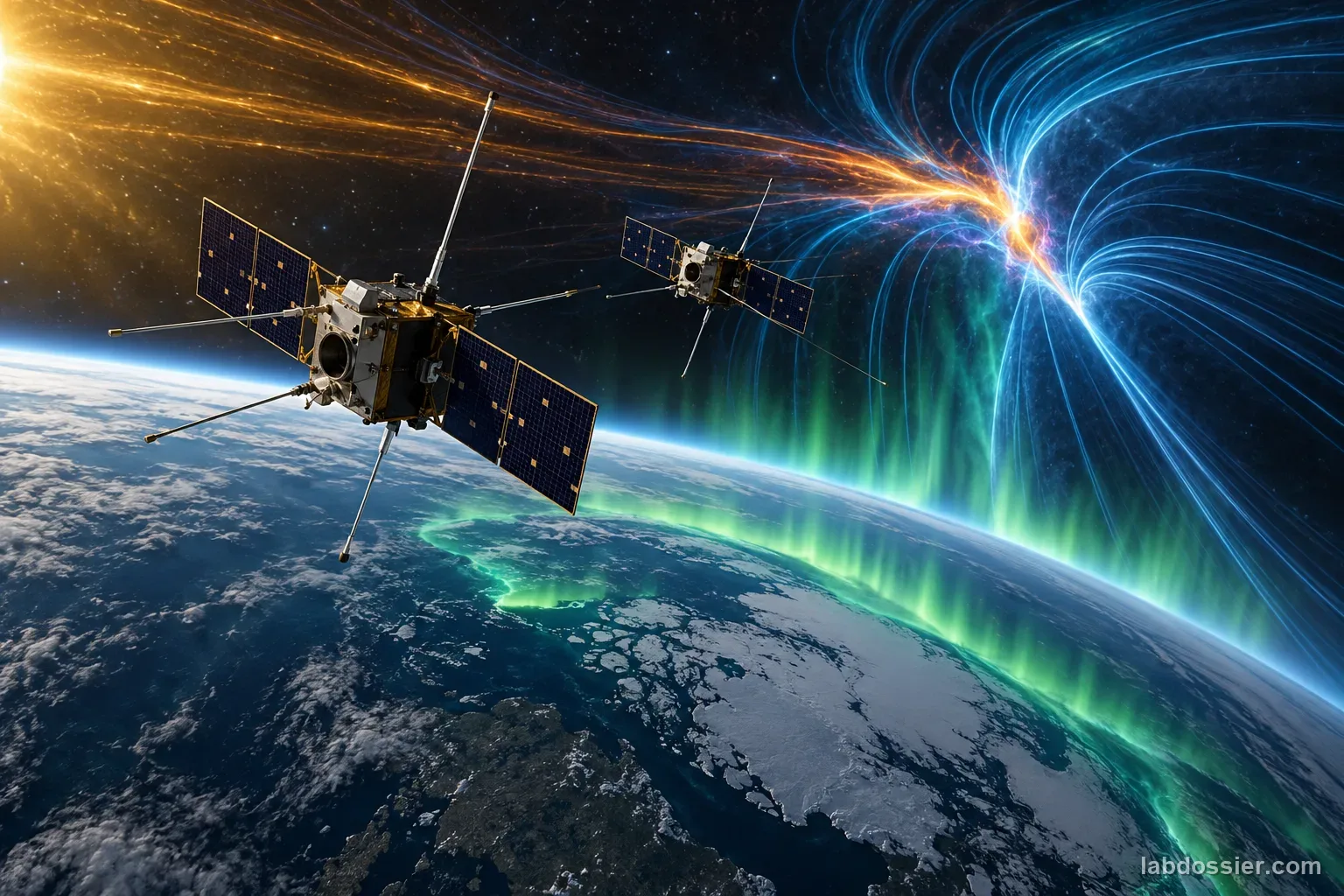
NASA's TRACERS mission studies reconnection near Earth's polar cusps, where solar wind and Earth's magnetosphere interact and particles can funnel into the upper atmosphere. The magnetosphere is not a perfectly closed shield: energy transfer, reconnection and particle entry are active parts of its behavior.
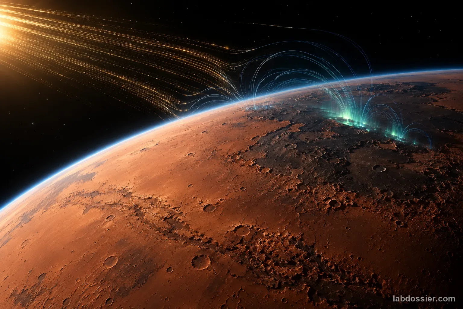
A July 2026 NASA summary of MAVEN findings explains that Mars lacks Earth's global magnetic field but has localized crustal magnetic regions. The study found a small-scale Dungey-like cycle and auroral processes over some of those regions. NASA said MAVEN lost contact in December 2025 and the spacecraft was declared unrecoverable in June 2026; archived mission data continue to support research. These observations show why field geometry and plasma interactions matter beyond the classroom equation.
14 // State the model's limits in the conclusion
Write the conclusion in two parts: report whether measured B changed as expected and whether the relative force proxy followed it; then name the assumptions. The comparison holds charge, speed and angle fixed and considers the magnetic-force term only.
Real solar-wind behavior depends on particle populations, velocities, pitch angles, electric fields, field topology, solar-wind pressure, reconnection and time. A bar magnet cannot test atmospheric loss, auroral brightness, satellite risk or planetary protection. Use NASA mission observations for those claims.
15 // Questions people ask
Does Earth's magnetic field simply repel solar particles?
No. The magnetic force can bend charged-particle motion, but real interaction depends on field and particle direction and on plasma processes. NASA describes reconnection at the magnetopause and particle entry near polar cusps, where some energy and particles reach the near-Earth environment.
Why does the angle matter in F = |q|vB sin θ?
Only the velocity component perpendicular to the field contributes to the magnetic-force magnitude. At 90° the force is largest for a given speed; moving parallel to the field gives zero magnetic force in this ideal equation.
Can this activity simulate a solar storm?
No. It measures a small magnet's local field and calculates a relative proxy for an assumed particle. It does not reproduce solar-wind plasma, real particle speeds, electric fields, Earth's geometry, radiation dose or storm effects.
Does Mars have a magnetic field like Earth?
NASA reports that Mars does not have a global magnetic field like Earth's. It has localized crustal magnetic regions, where MAVEN has observed complex interactions and auroras.
Why use a Hall sensor rather than iron filings?
A Hall sensor gives a repeatable numerical field reading at a marked point and direction, which can be compared across settings. Iron filings show a rough pattern but do not measure field strength and are not a model of charged solar particles.
16 // Keep going
Can you explain the investigation?
How does magnetic-field strength change the predicted force on an identical simulated charged particle? · Student Data Sheet
Question: For the same hypothetical charged particle and perpendicular motion, how does a change in measured magnetic-field strength change the magnetic-force proxy?
Hypothesis: If the measured magnetic-field strength increases while the hypothetical particle, speed and 90° motion angle remain fixed, then the calculated magnetic-force-per-unit-charge-speed proxy will increase in direct proportion to the measured field, because the magnetic part of the Lorentz force has magnitude |q|vB sin θ, so at 90° the sine term is one and the field magnitude is the changing factor.
Materials
- teacher-approved small classroom bar magnets
- Hall-effect field sensor or phone with a verified magnetometer and units
- nonmagnetic probe stand and marked spacer
- ruler, tape, calculator and raw-data sheet
Safety before starting
- Use a low-strength classroom bar magnet and Hall sensor or a verified phone magnetometer. Secure the magnet and probe on a stable nonmagnetic surface; never use loose iron filings, projectiles, high voltage, or powerful neodymium magnets.
- Keep magnets away from magnetic storage, watches, phones with sensitive components, and implanted or wearable medical devices. Follow manufacturer guidance, supervise the setup, and stop if a device is affected or the sensor overheats or behaves unexpectedly.
Lab notes
- For a charged particle, magnetic-force magnitude depends on charge, speed, field strength and the angle between velocity and field: F = |q|vB sin θ. Do not omit the angle or say every particle is repelled.
- Magnetic fields can guide, bend or trap charged particles. Earth's magnetosphere has polar cusps and reconnection; NASA has observed highly localized magnetic structures and auroras at Mars.
- A Hall sensor and tabletop magnet measure only a local classroom field. Never convert the reading directly into planetary field strength, particle radiation dose, atmospheric loss or human safety.
Variables
Independent: Measured magnetic-field magnitude at one fixed sensor point, changed by using different teacher-approved magnet configurations · Dependent: Relative magnetic-force proxy for the same hypothetical charged particle moving at 90° to the field
Keep constant: Use the same Hall sensor, probe location, probe orientation, magnet geometry or marked spacing, nearby metal, room setup, averaging time and hypothetical charge/speed/angle; change the field setting only
Procedure
- Set up a low-risk field measurement: Use a classroom Hall-effect magnetometer or a phone sensor only if its sensor type and units are known. Keep phones, magnetic storage media, watches and medical devices away from strong magnets; follow the device maker's guidance. Do not use loose iron filings, projectile particles, high-voltage equipment or powerful neodymium magnets. Mark one probe point on a nonmagnetic stand and record the probe axis.
- Choose three controlled field settings: Use teacher-approved small classroom magnets arranged to produce the same field direction at the marked point. Change one spacing or configuration variable to create low, medium and high settings; keep the probe, support and surrounding objects fixed. If changing the configuration rotates the field, record direction as well as magnitude and do not compare magnitudes as if direction were unchanged.
- Collect repeated sensor readings: Allow the sensor reading to settle, then record five values for each setting without touching the probe. Use the same averaging interval and remove or record the background field with the magnets absent. Keep every raw value; flag sensor overload, drift or a moved probe rather than silently deleting the reading. Calculate each setting's mean and range.
- Calculate only the bounded force proxy: For a hypothetical particle moving at 90° to the measured field, the magnetic-force magnitude is |q|vB. Because the classroom sensor does not provide a real solar particle's charge or speed, compare B-perpendicular itself or divide each reading by the lowest-setting reading. The ratio is a relative force proxy only when the same q and v are assumed; it is not a force in newtons, an observed particle path or a shielding score.
- Compare the equation model with NASA evidence: NASA describes Earth's magnetosphere as a large magnetic environment that interacts with solar wind. Its TRACERS mission measures changing reconnection events near the polar cusps, where particles can enter the near-Earth environment. NASA's 2026 MAVEN result describes much smaller, localized crustal magnetic structures at Mars and auroras associated with a miniature Dungey-like cycle. These observations show why a field does not simply repel every particle in the same way.
- Write the boundary before the conclusion: State that the controlled result is the relationship between a measured field and a mathematical force proxy for one fixed hypothetical particle. Real solar-wind motion depends on particle charge, mass, speed, pitch angle, electric and magnetic fields, plasma interactions, field geometry and time-varying reconnection. Magnetic forces act perpendicular to velocity and can bend or guide motion; they do no work on an ideal isolated particle by themselves and are not a universal barrier.
Record your observations
| Field setting | Raw B readings (µT) | Mean B (µT) | Range (µT) | Relative B / low setting | Sensor or setup note |
|---|---|---|---|---|---|
What the force equation does and does not predict
| Case | Model relationship | Interpretation limit |
|---|---|---|
A bar magnet, Earth and Mars are different systems
| System | What the source or model supports | What it cannot establish |
|---|---|---|
Answer key and expected pattern
If the probe geometry and field direction stay controlled, a higher measured B produces a proportionally higher force proxy for the same hypothetical charge and speed at 90°.
The relationship changes with angle: field-parallel motion has no magnetic force in the simple Lorentz-force equation, while perpendicular motion has the largest magnetic-force magnitude for the same speed.
The result is a mathematical comparison based on a local magnet measurement, not a simulated solar-particle stream or a measure of planetary shielding.
Remember: A magnetic field can bend charged-particle motion, but a stronger classroom magnet does not reproduce a planet's space environment. Interpret the data as a B-dependent force proxy for an identical hypothetical particle, then use NASA observations to explain geometry, reconnection and the limits of the simple model.