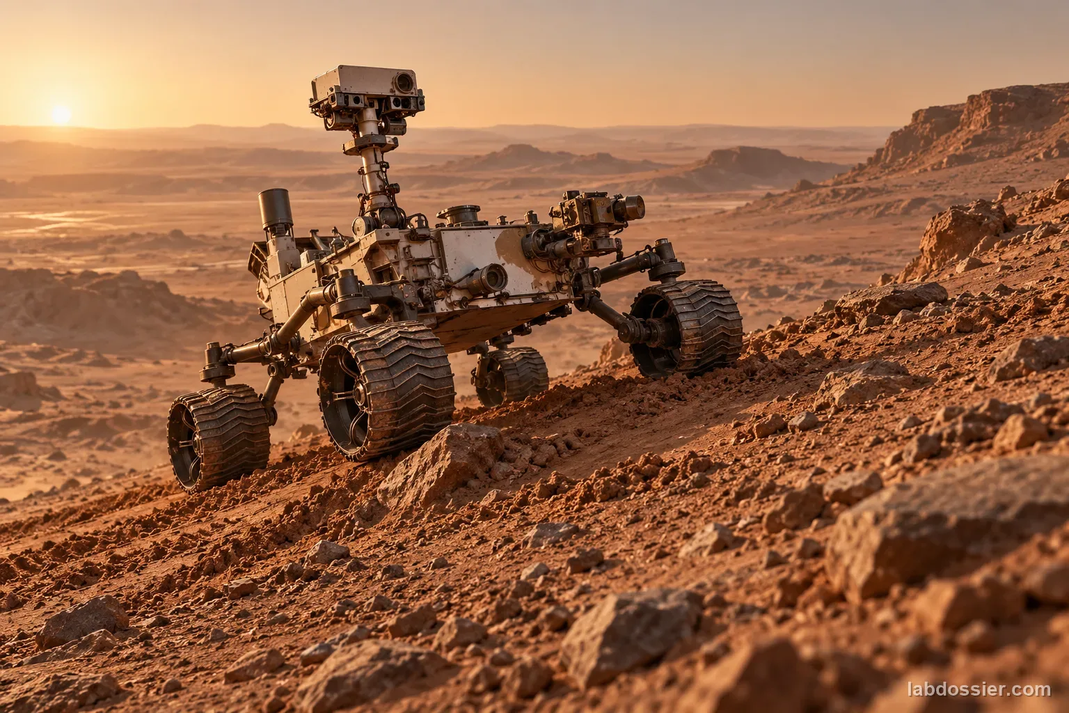
How does wheel tread change a rover model's slip and sinkage on a loose slope?
01 // Question
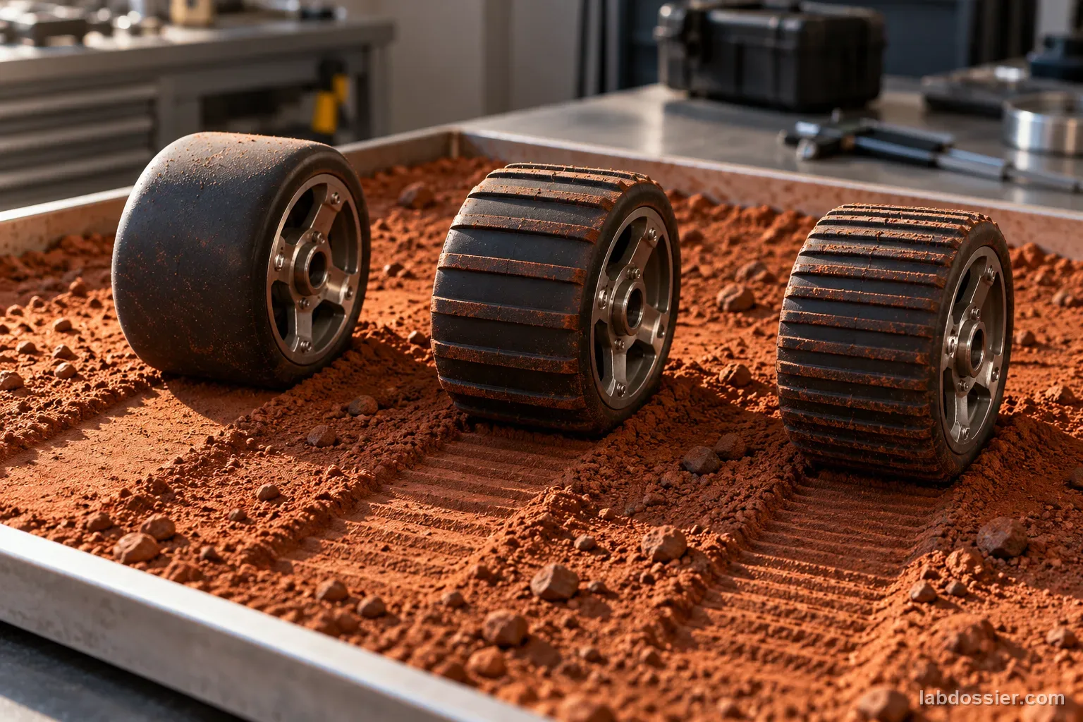
On one fixed loose-surface slope, how does the number of low-profile wheel ribs change model slip and sinkage under matched conditions?
The tabletop rig compares only wheel-surface patterns in one small, damp-sand tray. It does not simulate Mars gravity, regolith chemistry, vacuum, rover mass, six-wheel suspension, or provide a safe slope limit for a real mission.
02 // Variables
Independent
Tread pattern on the same-diameter test wheel- smooth sleeve
- four evenly spaced shallow ribs
- eight evenly spaced shallow ribs
Dependent
Distance-based slip proxy and vertical sinkage after three crank rotations- actual rig travel compared with three measured wheel circumferences
- estimated slip proxy as a percent
- sinkage depth in millimeters and any rut or side-slip note
03 // Hypothesis
IF a small rover model uses evenly spaced shallow ribs rather than a smooth wheel on the same loose-surface incline, THEN one ribbed pattern may travel farther per three rotations or sink less in this tray, BECAUSE tread geometry changes how a wheel pushes against loose grains, but the result also depends on grain packing, wheel load, slope and rib dimensions.
04 // Procedure
1. Build a contained, low-speed wheel test
Use a small hand-cranked single-wheel test rig or lightweight rover chassis with a visible wheel and fixed load. Fit three same-diameter, same-width and similar-mass sleeves: smooth, four shallow ribs, and eight shallow ribs. Secure the rig to a stable guide over a shallow tray; catch it with a stop and never use a person or animal as cargo. Keep the crank and wheel away from fingers while moving.
2. Prepare one repeatable loose surface
Place a shallow, level layer of clean commercial play sand in a lipped tray and dampen it just enough to reduce airborne dust. Use the same fill depth and a measured tamping routine for every reset. Set the ramp to 8° and mark the start and end. This contained material is only a classroom granular medium; moisture and grain shape make it unlike Martian regolith.
3. Measure each wheel's circumference
Before testing, roll each loaded wheel once over paper and measure its rolling circumference. Refit the same test wheel or sleeve without changing its diameter, width or load. Record the circumference because even small tread-height differences change the ideal distance for three rotations.
4. Run matched three-rotation trials
For each tread, reset and level the bed, return the rig to the start line and turn the crank exactly three slow rotations using a marked handle. Record actual travel along the ramp and sinkage at the wheel center. Complete five trials for each tread; use the same crank speed and mark any lateral slip, grain pile-up or inconsistent reset rather than silently dropping a run.
5. Calculate the model's slip proxy
Ideal rolling distance is three times that wheel's measured circumference. Calculate the classroom slip proxy as 100 × (ideal distance − actual travel) ÷ ideal distance. Keep the individual runs, then find the mean and range for each tread. Do not clip a negative value: if measured travel exceeds the ideal reference, recheck circumference, bed motion and direction, then report it as a model discrepancy rather than physical negative slip. This proxy assumes the rig's travel is along the wheel path; it is not NASA's onboard slip estimator and cannot predict a real rover's motion.
6. Change slope only in a separate test
After comparing tread at 8°, choose one wheel pattern using a rule written before looking at the result, such as the lowest median slip proxy. Test that wheel on a level tray and at 5° and 10°, keeping all other settings fixed and taking three repeats at each angle. Stop if the rig tips, leaves its guide or the bed moves as one slab; do not infer a safe Mars slope from these small angles.
Materials // Prepare the bench
- small hand-cranked single-wheel test rig or lightweight model chassis
- three matched same-diameter tread sleeves: smooth, four shallow ribs, eight shallow ribs
- stable guide rail and catch stop
- shallow lipped tray and clean commercial play sand
- ruler, angle gauge, caliper or paper circumference strip
- small fixed load, timer, calculator and data sheet
05 // Data table
| Tread | Trial | Wheel circumference (cm) | Ideal distance, 3 turns (cm) | Actual travel (cm) | Slip proxy (%) | Sinkage (mm) / notes |
|---|---|---|---|---|---|---|
| Smooth | 1 | |||||
| Smooth | 2 | |||||
| Smooth | 3 | |||||
| Smooth | 4 | |||||
| Smooth | 5 | |||||
| 4 shallow ribs | 1 | |||||
| 4 shallow ribs | 2 | |||||
| 4 shallow ribs | 3 | |||||
| 4 shallow ribs | 4 | |||||
| 4 shallow ribs | 5 | |||||
| 8 shallow ribs | 1 | |||||
| 8 shallow ribs | 2 | |||||
| 8 shallow ribs | 3 | |||||
| 8 shallow ribs | 4 | |||||
| 8 shallow ribs | 5 |
Wheel-pattern results stay tied to the tested setup
| Tread | Mean slip proxy | Range | Mean sinkage | What happened in the tray? |
|---|---|---|---|---|
| Smooth | ||||
| 4 shallow ribs | ||||
| 8 shallow ribs |
A model result is not a planetary mobility specification
| Factor | Classroom rig | Real rover consideration |
|---|---|---|
| Wheel and load | One small wheel with a fixed tabletop load | Full vehicle mass, wheel size, suspension and load sharing across wheels |
| Surface | Damp commercial play sand in a shallow tray | Site-specific grain size, cohesion, crust, rocks, moisture and temperature |
| Gravity and atmosphere | Earth gravity and room air | Mars gravity, low pressure, thermal cycling and dust |
| Control and risk | Three slow hand-crank rotations with a catch stop | Onboard slip estimation, traction control, route planning and hardware limits |
06 // What to expect
A ribbed tread may reduce the classroom slip proxy or sinkage in this prepared tray, but the best pattern cannot be assumed before data collection.
The rank order can change if soil packing, grain moisture, load, slope or rib geometry changes; report those conditions alongside the averages and ranges.
NASA's wheel and terrain work combines wheel design with route, suspension, soil, wheel-damage and traction-control considerations that the tabletop model does not reproduce.
07 // Lab notes
- Use a descriptive classroom slip proxy based on wheel circumference and measured travel. Do not present it as a flight rover's slip estimate or directly compare it with mission performance metrics.
- If actual travel exceeds the calculated ideal distance and the slip proxy is negative, retain and explain the value; check circumference measurement, bed movement and direction rather than clipping the result or calling it physical negative slip.
- NASA reports that rover traction, wheel wear, slope and terrain interact; design choices and safe driving tactics are mission- and surface-specific.
- The 2026 adaptive-grouser study on arXiv is marked under review. Its trial outcomes apply to the authors' test configuration and do not validate performance on Mars.
08 // Remember
Ribs can change wheel grip, but no single tread wins on every loose surface or slope. Compare matched wheels on one repeatable surface, report slip and sinkage separately, and treat the result as a local model rather than a Mars mobility limit.
09 // Wheel grip depends on the wheel and terrain together
A rover wheel must carry load, deform or press into the surface, and create enough traction to move without excessive slip or sinkage. Raised ribs, often called grousers, can push against granular material. Their number, height, direction and spacing interact with soil grain size, compaction, wheel size, load and slope. A tread that helps on loose sand may not be best on rock or hard crust.
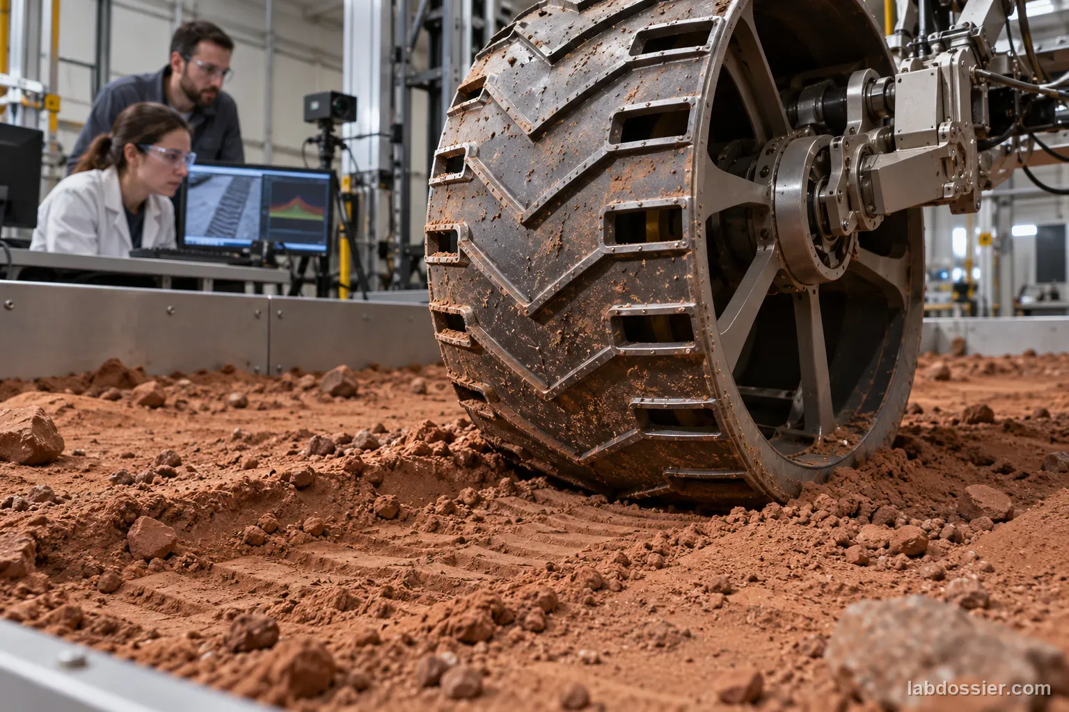
NASA and JPL test full-scale or single-wheel systems against controlled surfaces because a rover's mobility depends on more than visible tire texture. Wheel material and damage, chassis suspension, speed commands, slope, route choice, gravity and soil mechanics all contribute.
10 // Build a contained, low-speed wheel test
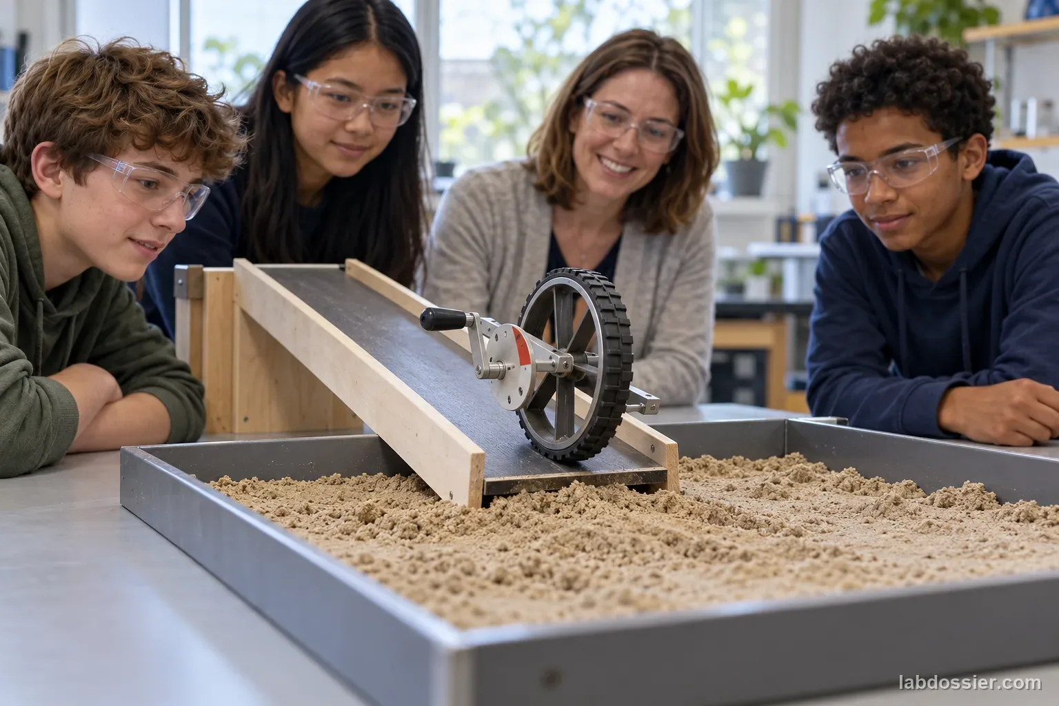
This model uses one driven test wheel and a fixed load, similar in purpose (not scale) to a single-wheel soil tester. Compare one smooth sleeve, one with four shallow ribs and one with eight shallow ribs. Keep their diameter, width, mass and material as close as possible; measure each circumference so the expected travel is calculated from that exact wheel.
The hand crank makes three slow rotations on a guide over a shallow tray. A catch stop prevents the small rig from running off the ramp. The design gives learners a direct way to compare rotation with progress without launching a vehicle, using a fast motor or sending anyone down a slope.
11 // Prepare one repeatable loose surface
Use the same tray, sand depth, moisture and packing routine for each run. NASA's 2014 Curiosity wheel tests examined loose granular soil, denser high-shear soil and bedrock-like material, demonstrating why one ground condition cannot stand in for all others. The classroom's slightly damp commercial sand controls dust but is not chemically or mechanically identical to dry Martian regolith.
Set the model ramp to 8 degrees and level the sand after each trial. A tilted tray that shifts, a changing fill depth, or moisture that varies between runs can matter as much as a tread change. Record these conditions and repeat the reset routine consistently.
12 // Calculate a bounded slip proxy
For three crank turns, ideal rolling distance equals three times the measured wheel circumference. Compare it with the actual distance the rig advances: slip proxy (%) = 100 × (ideal distance − actual distance) ÷ ideal distance. A larger positive value means less forward progress per expected rolling distance in this setup. Do not clip a negative result: if measured travel exceeds the ideal reference, check the circumference, bed movement and direction, then report it as a model discrepancy rather than physical negative slip. If the wheel turns backward or the rig is pushed rather than driven, stop and clarify the sign convention before calculating.
Measure sinkage separately at the wheel center after each run. One tread could make the rig move farther but cut a deeper rut. Keep those outcomes as separate evidence; do not combine them into a single winner score unless you state how travel, soil disturbance, energy and risk are weighted.
13 // Change slope only in a separate test
The first comparison holds the slope fixed and varies tread. The extension chooses one tread using a prewritten rule, then tests level, 5-degree and 10-degree surfaces with fresh matched resets. The NASA/JPL 2016 Opportunity report gives a vivid real example: during a steep Martian climb, wheel rotation that could have produced about 20 meters of movement on firm ground resulted in only about 9 centimeters of actual progress because slip was so great.
That mission event does not provide a safe universal slope limit; the rover, site, traction, target, measurement and operational decision were specific. Never scale the classroom angle into a route recommendation for a Mars rover.
14 // Interpret the result with rover engineering context
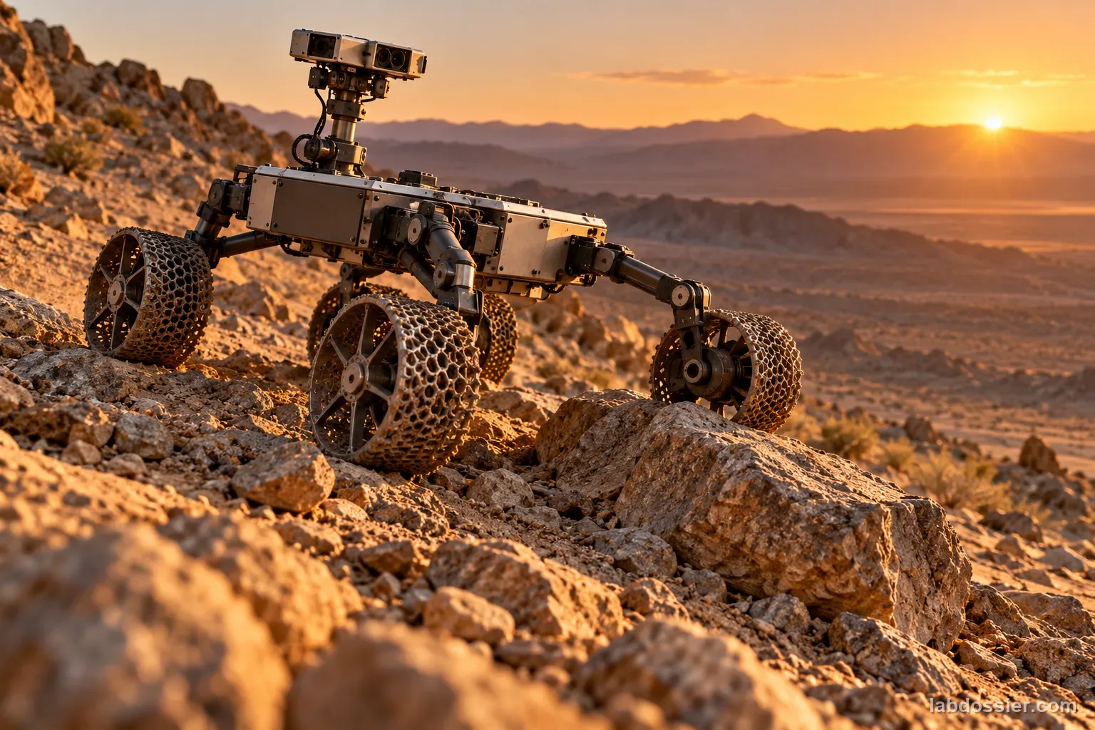
A 2026 arXiv preprint under review reports 750 tests of an adjustable-grouser prototype across vinyl, rock, pea gravel and sand packing states. Its authors report reduced slip for some adaptive settings, while also finding that one grouser height did not minimize slip across every tested terrain. These are results from that prototype and its Earth-based test conditions, not validation on Mars.
NASA's 2026 ERNEST field campaign adds context that future mobility also includes active suspension, articulated mesh wheels and autonomy. The prototype traveled across a desert and had earlier tested obstacles and slopes in a Mars Yard, but it is a technology testbed for potential missions, not a flight rover demonstration on the Moon or Mars.
15 // Questions people ask
Why might ribs help a rover wheel?
Raised tread elements can push against loose grains and change traction. Their benefit depends on height, spacing, direction, wheel load, soil properties and slope; a pattern that helps in one surface can perform differently in another.
Does a lower classroom slip proxy mean a wheel would work best on Mars?
No. It means only that this test rig traveled farther per calculated wheel rotation under the tested tray conditions. Mars soil, gravity, vehicle scale, suspension, wheel damage and driving controls differ substantially.
Why record sinkage as well as distance?
A wheel might travel farther while digging a deeper rut, or reduce sinkage while sliding sideways. Keeping separate measurements shows trade-offs that one score would hide.
Do NASA rovers use traction control?
NASA/JPL's Curiosity team developed terrain-adaptive traction control that adjusts wheel speeds using rover state and estimated wheel-terrain contact. Different missions use different mobility hardware and software.
What does the 2026 adjustable-grouser study show?
The under-review preprint reports tests of an adjustable-grouser prototype across several Earth surfaces and packing states. It suggests no single grouser height minimized slip across every tested surface. Those results are not a demonstration on Mars or a flight qualification.
16 // Keep going
Can you explain the investigation?
How does wheel tread change a rover model's slip and sinkage on a loose slope? · Student Data Sheet
Question: On one fixed loose-surface slope, how does the number of low-profile wheel ribs change model slip and sinkage under matched conditions?
Hypothesis: If a small rover model uses evenly spaced shallow ribs rather than a smooth wheel on the same loose-surface incline, then one ribbed pattern may travel farther per three rotations or sink less in this tray, because tread geometry changes how a wheel pushes against loose grains, but the result also depends on grain packing, wheel load, slope and rib dimensions.
Materials
- small hand-cranked single-wheel test rig or lightweight model chassis
- three matched same-diameter tread sleeves: smooth, four shallow ribs, eight shallow ribs
- stable guide rail and catch stop
- shallow lipped tray and clean commercial play sand
- ruler, angle gauge, caliper or paper circumference strip
- small fixed load, timer, calculator and data sheet
Safety before starting
- Use only a lightweight hand-cranked rig, shallow guided ramp and securely lipped tray. Secure the catch stop and fixed load before each run; never ride, push a person or use a fast motorized vehicle on the ramp.
- Slightly dampen clean commercial sand to reduce airborne dust, keep it below tray height, do not blow or throw it, and keep faces away during handling. Wear splash/dust eye protection if the supervising adult's risk check calls for it, then wash hands and clean the work surface after use.
- Keep fingers clear of the rotating crank and wheel, stop if the rig tips or leaves its guide, and use adult supervision when adjusting the ramp or load. Do not treat classroom results as a Mars slope-safety rule.
Lab notes
- Use a descriptive classroom slip proxy based on wheel circumference and measured travel. Do not present it as a flight rover's slip estimate or directly compare it with mission performance metrics.
- If actual travel exceeds the calculated ideal distance and the slip proxy is negative, retain and explain the value; check circumference measurement, bed movement and direction rather than clipping the result or calling it physical negative slip.
- NASA reports that rover traction, wheel wear, slope and terrain interact; design choices and safe driving tactics are mission- and surface-specific.
- The 2026 adaptive-grouser study on arXiv is marked under review. Its trial outcomes apply to the authors' test configuration and do not validate performance on Mars.
Variables
Independent: Tread pattern on the same-diameter test wheel · Dependent: Distance-based slip proxy and vertical sinkage after three crank rotations
Keep constant: Use the same wheel core and outer diameter, rig and vertical load, 8° ramp, tray, damp sand depth and leveling/packing routine, start line, three crank turns, crank speed, measuring method and reset procedure; change tread only
Procedure
- Build a contained, low-speed wheel test: Use a small hand-cranked single-wheel test rig or lightweight rover chassis with a visible wheel and fixed load. Fit three same-diameter, same-width and similar-mass sleeves: smooth, four shallow ribs, and eight shallow ribs. Secure the rig to a stable guide over a shallow tray; catch it with a stop and never use a person or animal as cargo. Keep the crank and wheel away from fingers while moving.
- Prepare one repeatable loose surface: Place a shallow, level layer of clean commercial play sand in a lipped tray and dampen it just enough to reduce airborne dust. Use the same fill depth and a measured tamping routine for every reset. Set the ramp to 8° and mark the start and end. This contained material is only a classroom granular medium; moisture and grain shape make it unlike Martian regolith.
- Measure each wheel's circumference: Before testing, roll each loaded wheel once over paper and measure its rolling circumference. Refit the same test wheel or sleeve without changing its diameter, width or load. Record the circumference because even small tread-height differences change the ideal distance for three rotations.
- Run matched three-rotation trials: For each tread, reset and level the bed, return the rig to the start line and turn the crank exactly three slow rotations using a marked handle. Record actual travel along the ramp and sinkage at the wheel center. Complete five trials for each tread; use the same crank speed and mark any lateral slip, grain pile-up or inconsistent reset rather than silently dropping a run.
- Calculate the model's slip proxy: Ideal rolling distance is three times that wheel's measured circumference. Calculate the classroom slip proxy as 100 × (ideal distance − actual travel) ÷ ideal distance. Keep the individual runs, then find the mean and range for each tread. Do not clip a negative value: if measured travel exceeds the ideal reference, recheck circumference, bed motion and direction, then report it as a model discrepancy rather than physical negative slip. This proxy assumes the rig's travel is along the wheel path; it is not NASA's onboard slip estimator and cannot predict a real rover's motion.
- Change slope only in a separate test: After comparing tread at 8°, choose one wheel pattern using a rule written before looking at the result, such as the lowest median slip proxy. Test that wheel on a level tray and at 5° and 10°, keeping all other settings fixed and taking three repeats at each angle. Stop if the rig tips, leaves its guide or the bed moves as one slab; do not infer a safe Mars slope from these small angles.
Record your observations
| Tread | Trial | Wheel circumference (cm) | Ideal distance, 3 turns (cm) | Actual travel (cm) | Slip proxy (%) | Sinkage (mm) / notes |
|---|---|---|---|---|---|---|
Wheel-pattern results stay tied to the tested setup
| Tread | Mean slip proxy | Range | Mean sinkage | What happened in the tray? |
|---|---|---|---|---|
A model result is not a planetary mobility specification
| Factor | Classroom rig | Real rover consideration |
|---|---|---|
Answer key and expected pattern
A ribbed tread may reduce the classroom slip proxy or sinkage in this prepared tray, but the best pattern cannot be assumed before data collection.
The rank order can change if soil packing, grain moisture, load, slope or rib geometry changes; report those conditions alongside the averages and ranges.
NASA's wheel and terrain work combines wheel design with route, suspension, soil, wheel-damage and traction-control considerations that the tabletop model does not reproduce.
Remember: Ribs can change wheel grip, but no single tread wins on every loose surface or slope. Compare matched wheels on one repeatable surface, report slip and sinkage separately, and treat the result as a local model rather than a Mars mobility limit.